Patents
Second Patent Filing
A second UK patent application was made on 13 February 2022. This comprises several new inventions relating to the implementation of the PowerMaximiser concept. Divisional applications based on this priority date are expected. Contact us for partnering arrangements. Scroll down to "Second Patent Application" to see the text and drawing sources used for this application.
First Patent Filing.
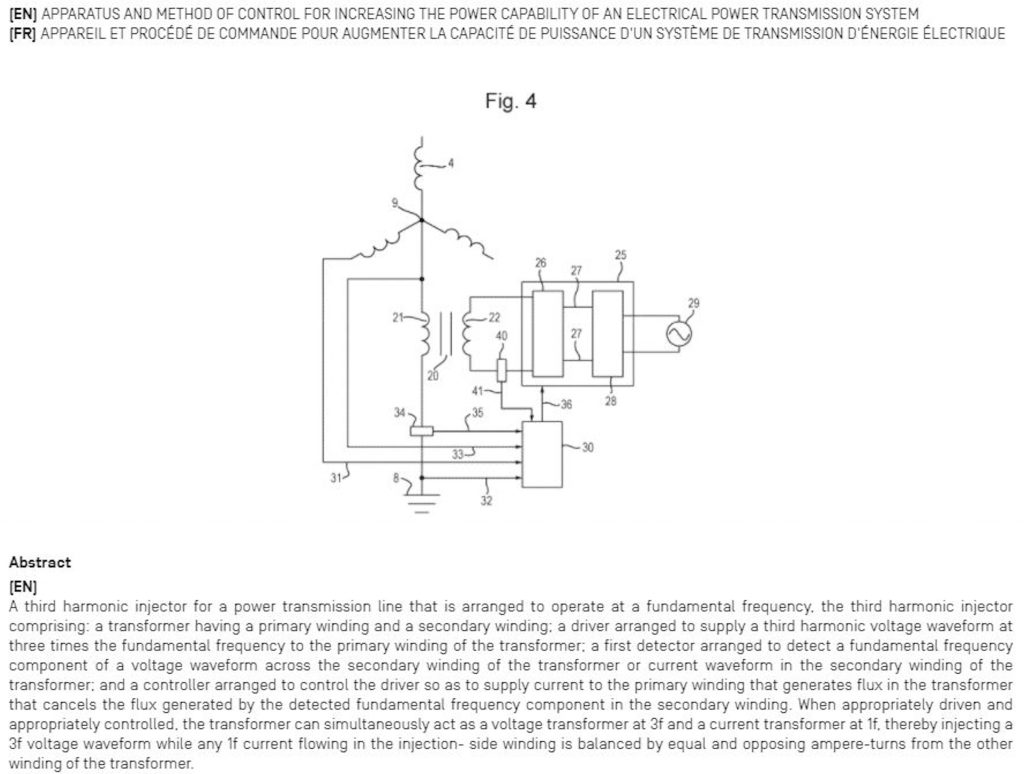
A patent application for the third harmonic star-point injector arrangement was filed with the UK patent office on 18 September 2019. "Apparatus and method of control for increasing the power capability of an electrical power transmission system". GB1913453.5. We received an encouraging report from the UK examination.
The key concepts in this application are:
The injector transformer operates as a voltage transformer at triple frequency and as a current transformer at fundamental frequency. This makes it appear transparent to fundamental frequency currents, particularly zero-sequence currents resulting from an unbalanced load on the transmission system.
Flux at fundamental frequency is suppressed in the injector transformer core by detecting any deviation of the transformer output voltage waveform from the desired triple frequency waveform and by the application of a corrective current in the input winding.
Fault-level currents are transiently handled by allowing the transformer to saturate thereby creating a low impedance connection to ground. Additional fault-handling capability is provided by an anti-parallel pair of SCRs across the transformer which are activated at the appropriate moment.
PCT Filing.
The patent application has gone forward to the PCT stage (PCT/GB2020/052257) and again the examination report was positive with respect to key claims.
The patent application was published on 25 March 2021. To see the application in full go to www.wipo.int/pctdb
and enter WO2021/053340
The application enters national phase in March 2022.
Strategy.
The national phase of securing a patent is an expensive activity. As is the building of demonstrators at the power levels commonly found in grid and distribution systems. Hence we are engaged in a partner search. We see the present priority to be the securing of further patents at this stage since we have additional ideas which are as yet unprotected but which have the potential to contribute further to the plug-and-play concept.
Patent Application Key Drawing and Abstract
Second Patent Application. (13 Feb 2022)
Increasing the power capacity of a three-phase electrical power transmission system by combining it with a triple-frequency power system
Setting
Adding 1/6th third harmonic to the ac supply waveform (a sinusoid) permits the maximum theoretical power capability of a transmission system to be increased by 33%. Alternatively the power can be kept constant and voltage increased and the current reduced, thereby lowering line losses due to resistance by up to 33%.
Third harmonic injection gives some of the benefits of DC transmission while keeping the immense advantages of AC. Third harmonic injection in a section of a transmission system allows that section to operate for most of each cycle at close to peak allowable voltage. The technology is applicable to distribution systems as well as grid transmission.
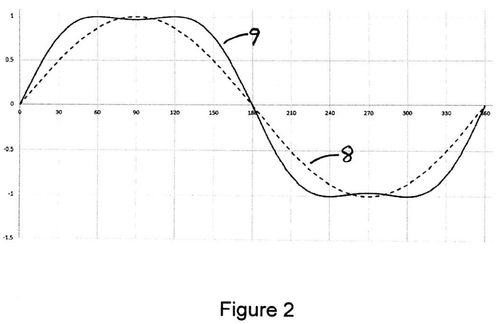
Adding 1/6th of third harmonic lowers the peak value of a sinusoidal waveform by a factor of 0.866. Restoring the combined waveform to the allowable line-to-ground peak value for the transmission line raises the fundamental voltage by a factor of 1.156. This principle has been widely used for many years to raise the output voltage in three-phase inverters. ("The use of harmonic distortion to increase the output of a three-phase PWM inverter". Houldsworth J.A. and Grant D.A. IEEE Transactions of the Industry Applications Society, Sept 1984, pp 1224-1228). The P(max) of a power transmission line is proportional to V2. Therefore the raising of the fundamental voltage theoretically permits P(max) to be increased by a factor of 1.33. In Figure 2 the dashed line waveform 8 is the line-ground waveform before the addition of the third harmonic. The solid line waveform 9 is the line-ground voltage after the addition of the third harmonic and amplification by 1.156.
In conventional ac power systems which employ a pure sine wave, the line-to-line voltage is limited by the peak permitted line-to-ground voltage. By breaking that link by adding a third harmonic we allow the line-to line voltage to be increased by 15.6% and the power limit is increased by up to 33%.
The benefits of third harmonic addition are either more power capacity or reduced losses (if power transmission is kept the same and current is reduced in proportion to the voltage increase).
The third harmonic is stripped out as the power passes through the receiving end transformer. Or if it is advantageous, it can be retained and taken out later – or not at all depending on the end use.
A pure sine wave uses the maximum allowed line-ground voltage once every half cycle. A sine wave plus third harmonic uses the maximum allowed line-ground voltage twice every half cycle. Hence adding a third harmonic moves the performance of an ac line closer to that of a dc line. By adding third harmonic power transmission, fundamental power transmission is enhanced. To achieve the ideal voltage waveform along the whole line length, there must be power flow due to the third harmonic voltage waveform as well as power flow due to the fundamental frequency voltage waveform. So the process by which power flow due the 50Hz or 60Hz voltage waveforms is increased may be achieved by adding to the system power flow due to the 150Hz or 180 Hz voltage waveforms.
Means by which third harmonic voltage waveforms may be injected into a three-phase power line are described in patent application WO2021/053340
There are two modes in which a transmission line with third harmonic injection can be operated.
(1) Raise the power rating by up to 33% without raising the line-ground voltage rating. The fundamental line-line voltage is raised by 15.6%. P ∝ V2.
(2) Keep the power (VA) rating the same but reduce the line conductor losses. The fundamental voltage is raised by 15.6%. The current is reduced by 15.6%. I2R losses are reduced by 33%.
For a three-phase transmission line, power flow may approximately be expressed as:
P = V2 Sinδ / X
where
P is the total average power for the three phases
V is the working line-to-line voltage,
δ is the phase angle difference between the ends of the line
X is the reactance of the line.
Alternatively, the power flow may approximately be expressed as:
P = 3 V2 Sinδ / X
where:
P is the total average power for the three phases
V is the working line-to-ground voltage,
δ is the phase angle difference between the ends of the line
X is the reactance of the line.
In a three-phase transmission line in which only one (fundamental) frequency is employed, power is only due to positive sequence currents, the vectorial sum of which at each end of the line is zero. With no return current the line reactance per phase is approximately half the loop inductance of that of a 2-wire system (or equal to the inductance of a single side of the loop). It should be noted that while the inductance tends to dominate in a power line, resistance may be a significant component of the line impedance.
Expanding the equation P = 3 V2 Sinδ / X gives us some insights.
P = 3 x V x Vsinδ /X = 3 x Voltage(Line-Ground) x Current
The current in this equation is current at fundamental frequency. The in-phase component conveys power.
By adding a third harmonic and amplifying the waveform there is an immediate gain in Voltage (15.6%).
The current available is immediately increased by 15.6% (since it is a function of V in the equation above).
The amount of in-phase current which is caused to flow (node to node) is also determined
by how much we swing δ (or δ is swung for us – by the generator source or by quadrature voltage injection ). X is fixed. Stability considerations limit δmax.
Conductor losses may or may not be a limiting factor. Considerations include conductor weight, cost and sag). Some VAR flow is generated by a swing of δ. This is controllable by altering the relative magnitudes of Vsend and Vreceive. This voltage difference will also be needed to attend to the IR drop in each line.
The invention
An object of the invention is the superposition of triple-frequency power transmission on a fundamental frequency power line to increase the power capability of the fundamental frequency transmission system.
A further object of the invention is the use of a floating delta winding in a three-phase transformer to lower the zero-sequence inductance of the transformer.
A further object of the invention is the combination of triple harmonic injection (for increasing the power capability of a transmission line) with quadrature voltage injection (for the control of power and VAR flow at fundamental frequency) allowing sharing of power electronics components and equipment used in the implementation of these two system objectives.
A further object of the invention is quadrature voltage injection at the star point of the star winding of a three-phase transformer so that the power electronic quadrature voltage injectors are ground referenced.
A further object of the invention is the use of transformerless combined triple-harmonic and quadrature-voltage injectors which have zero impedance with respect to zero-sequence fundamental-frequency current.
A further object of the invention is the provision of booster transformers added to the three-phase transformers at each end of the transmission line with the purpose of adding 15.6% voltage at each end of the transmission line in order to fulfil the requirement of power capability increase by the addition of a third harmonic in retrofit and other situations.
Figures
The present invention will further be described, by way of example, with reference to the accompanying drawings.
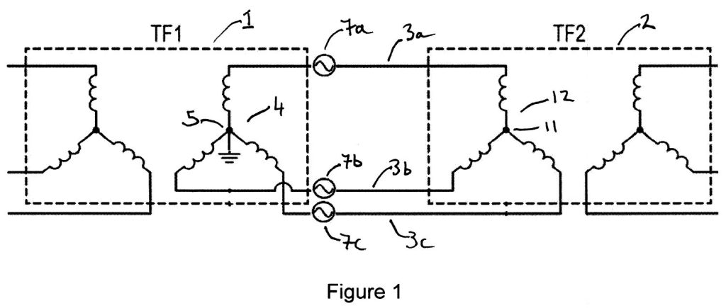
Figure 1. A three-phase power line with series third harmonic injection at one end and a star winding at the other.
Figure 2. A sine wave and a sine wave of increased amplitude plus a triple-frequency sine wave.
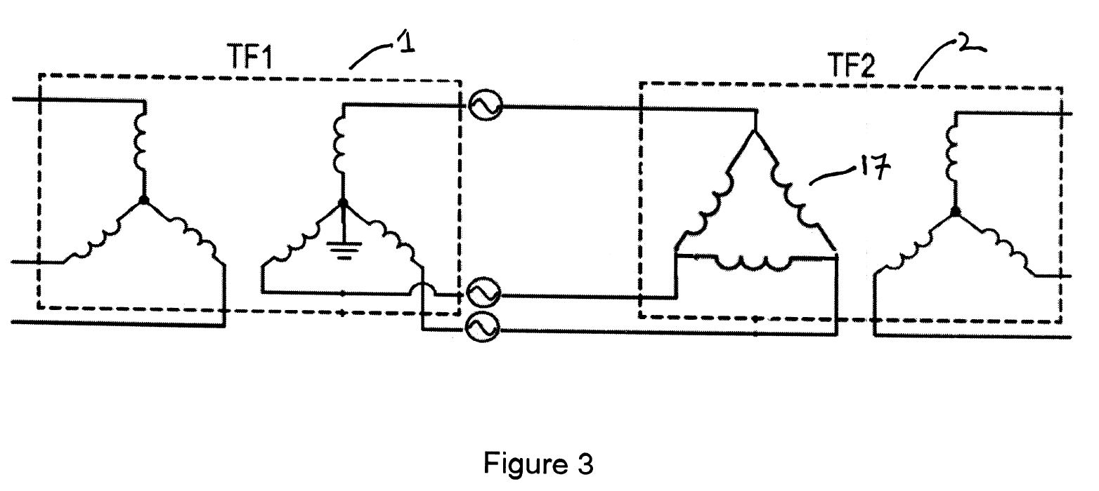
Figure 3. A three-phase power line with series third harmonic injection at one end and a delta winding at the other.
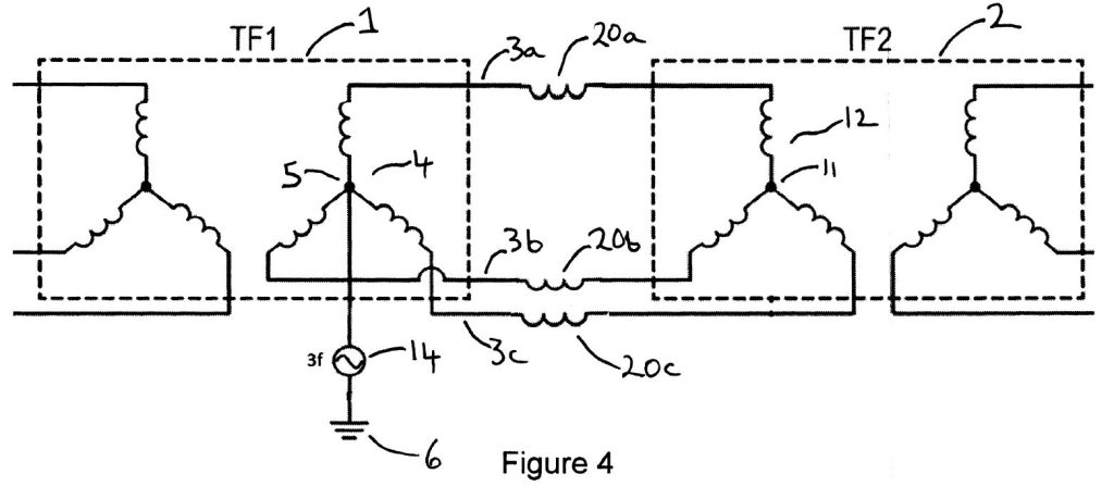
Figure 4. A three-phase power line including line inductances with star-point third harmonic injection at one end and a star winding at the other.
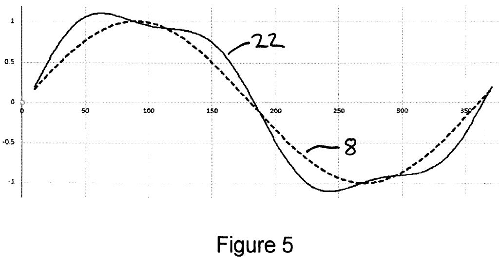
Figure 5. Distortion of the sine-plus-third-harmonic waveform due to incorrect phase relationship between the two components.
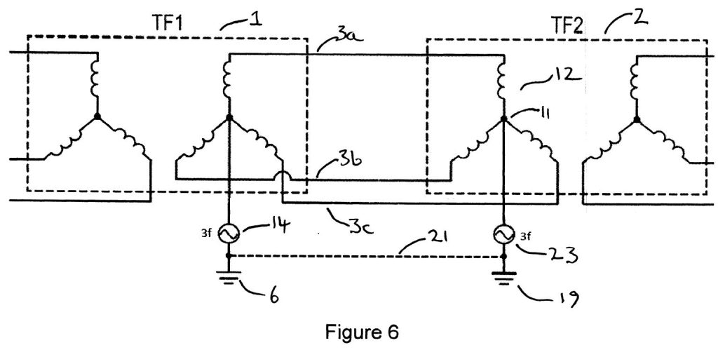
Figure 6. A three-phase power line with star-point third harmonic injection at both ends.
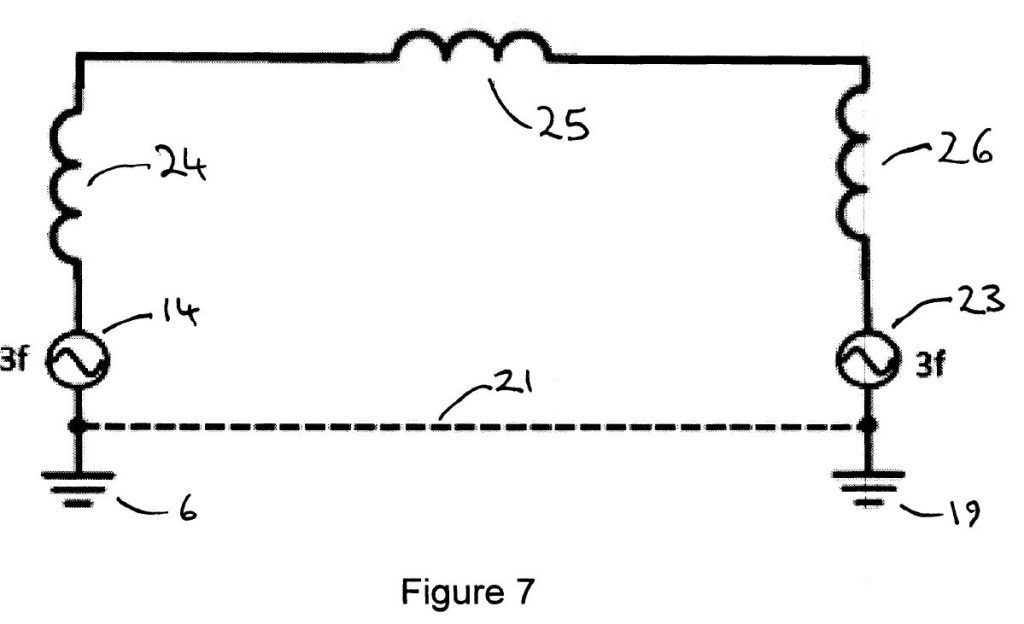
Figure 7. A single-phase equivalent circuit of the triple-frequency circuit.
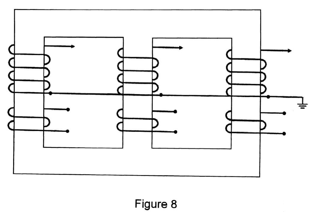
Figure 8. A three-limb three-phase transformer.
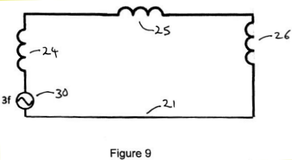
Figure 9. A single-phase equivalent circuit of the triple-frequency circuit with the two injectors combined into a single source.
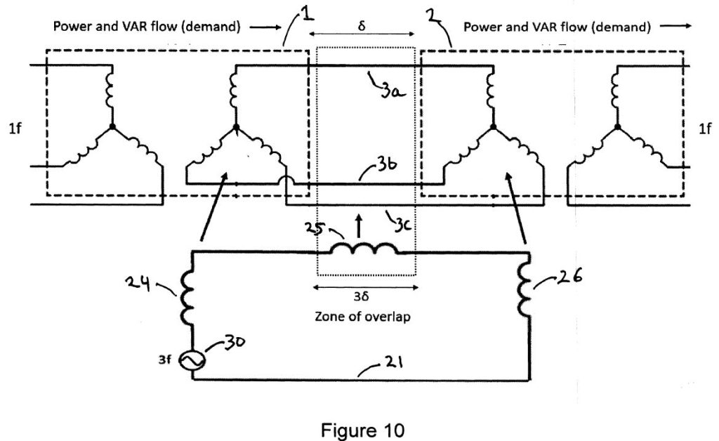
Figure 10. The fundamental-frequency and triple-frequency circuits overlaid.
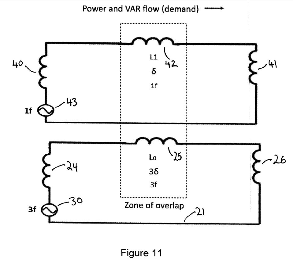
Figure 11. The fundamental-frequency and triple-frequency both represented by single-phase equivalent circuits and overlaid.
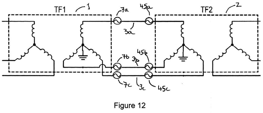
Figure 12. A three-phase power line with series third harmonic injection at both ends.
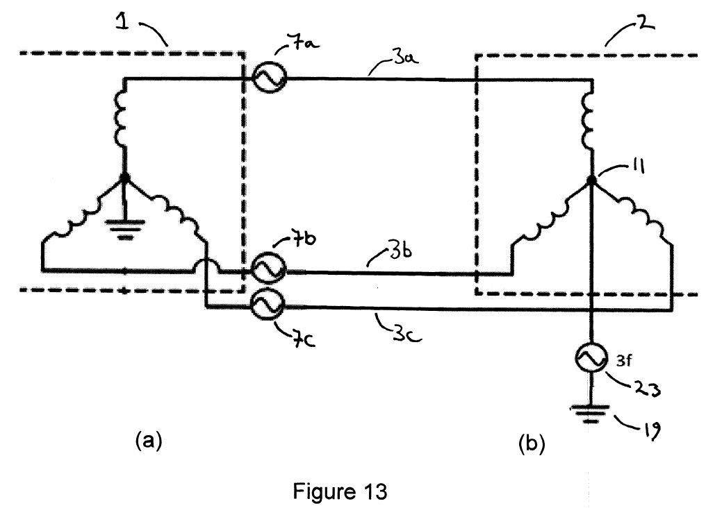
Figure 13. A three-phase power line with series third harmonic injection at one end and star-point injection at the other.
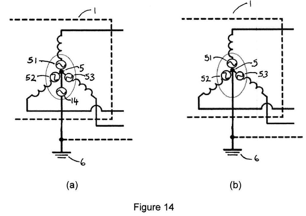
Figure 14. (a) Star point injection of both the triple-harmonic voltage waveform and a quadrature voltage waveform of fundamental frequency at the star point. (b) Star point injection of both the triple-harmonic voltage waveform and a quadrature voltage waveform of fundamental frequency at the star point using one injector per phase.
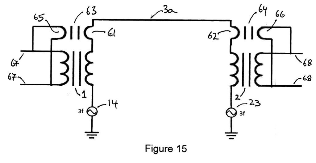
Figure 15. Booster transformers used to increase the amplitude of the fundamental voltage waveforms by 15.6%.
Description
Figure 1 shows an ac three-phase electrical power transmission system, consisting of three lines 3a,3b and 3c.The lines 3a, 3b,3c may be overhead wires or underground cables and are insulated from the earth by being suspended from insulators in the case of overhead lines or by being wrapped in insulating material in the case of cables. In an overhead transmission line each wire (3a, 3b, 3c) may consist of a number of conductors in parallel. The voltage at which the power transmission line can operate is set by the voltage withstand capability of the insulators or insulation. The electrical power transmission arrangement is completed by a sending end transformer 1 and a receiving end transformer 2. It is assumed that power flows from the transformer 1 to the transformer 2 via the lines 3a, 3b, 3c. However ac electrical power lines are capable of carrying power in either direction so the designation of transformer 1 as the sending end transformer and transformer 2 as the receiving end transformer is a convention adopted here for the purpose of illustration. The three-phase output winding 4 of the sending end transformer 1 is arranged in star with its star point 5 connected to ground 6.
To increase the power capability of the transmission line a third harmonic voltage of one-six the amplitude of the line-to-ground voltage waveform may be added to each of the outputs of the sending-end transformer 1 by means of series voltage injectors 7a, 7b and 7c.
Figure 2 illustrates the principle employed to increase the power capability of the line by the use of third harmonic injection. Waveform 8 represents the line-to ground waveform normally employed in ac power lines – that is a sinusoid of one frequency. Waveform 9 shows the same waveform but with a one-sixth amplitude (of the fundamental) triple frequency (third harmonic) waveform added in the appropriate phase to the fundamental and then with the overall amplitude of the composite waveform increased by 15.6%. Hence the amplitude of the fundamental waveform is increased by 15.6% without increasing the peak value of waveform 9 above the peak value of waveform 8.
Returning to Figure 1, the triple harmonic waveforms injected into lines 3a, 3b, 3c are cophasal. Because the star point 11 of the input three-phase winding 12 of the receiving end transformer 2 is floating, the third harmonic voltage waveforms are effectively stripped out at transformer 2 since voltage of the star point 11 follows the third harmonic voltage waveform. The third harmonic voltage waveform therefore only exists between the sending end transformer 1 and the receiving end transformer 2. The theoretical maximum power capability of the power line is increased by 33% as described above. The power that may be sent through transformers 1 and 2 may still be limited by the power capabilities of the input side of transformer 1 and the output side of transformer 2 and suitable changes must be made to the transformers to allow them to have a power throughput which matches the new power capability of the power transmission line.
Figure 3 shows a similar arrangement to Figure 1 but with the three-phase input winding 17 of transformer 2 arranged in delta. As in Figure 1 there is no third harmonic current flow and the whole delta winding has a third harmonic voltage waveform added to it.
A disadvantage of the arrangements shown in Figures 2 and 3 is that the full line current flows through the third harmonic injectors 7a, 7b, 7c. Hence the VA rating of the injectors is 1/6th of the line to ground voltage at third harmonic frequency multiplied by the full rated line current at fundamental frequency. Hence each injector has 1/6th the VA rating of each phase of the transformers 1 and 2.
Figure 4 shows an alternative method of injecting the third harmonic voltage waveform. The star point 5 of sending end transformer 1 is connected to a third-harmonic voltage injector 14 which injects a third harmonic voltage waveform of 1/6th amplitude of the fundamental voltage waveform at star point 5. This waveform is therefore simultaneously injected into the voltage-ground waveform of all three lines 3a, 3b, 3c. The positive and negative sequence sets of current flowing in the transmission line will sum to zero at the star point 5. Hence the injector 14 carries only the zero sequence currents in the three lines 3a, 3b, 3c. Zero sequence currents will flow when the load on the transmission line is unbalanced or there is an asymmetrical fault somewhere on the system. The use of an injector at the star point 5 could place an impedance at fundamental frequency between the star point 5 and earth 6. WO2021/053340 describes an invention which allows a triple harmonic voltage to be injected while maintaining negligible impedance between the star point 5 and earth 6.
In Figure 4, for each of the lines ( 3a, 3b, 3c ) the inductance has been included ( 20a, 20b, 20c ). The basic mechanism for causing power to flow along the transmission line from sending end to receiving end is to advance the phase angle of the sending end voltage waveforms (with respect to the phase angle of the receiving end). If the resistance of the lines is neglected, this causes a current to flow along each line and these currents are largely in-phase with the respective receiving end voltage waveforms. The difference in phase angle between the sending end voltage waveforms and the receiving end voltage waveforms of each phase is linearly distributed along the length of each line (3a, 3b, 3c),
Figure 5 shows how the change of phase angle of the voltage waveform along the line presents a difficulty for the third harmonic injection principle. The third harmonic waveform is injected into the lines (3a, 3b, 3c) at the sending and has the same phase angle along the whole length of the each line. While the third harmonic waveform will have the ideal relationship to the fundamental waveform at the sending end of the lines (3a, 3b, 3c) the phase relationship will be non-ideal at other points along the lines with the maximum error occurring at the receiving end of the lines (3a, 3b, 3c). The effect of this can be seen in the distortion of the sine-plus-third-harmonic waveform shown in Figure 5 in which the waveform 8 is the fundamental frequency waveform in each line before the addition of the third harmonic and before a 15.6% increase in the amplitude of the fundamental. The waveform 22 is the fundamental frequency waveform in each line after the addition of the third harmonic and a 15.6% increase in the amplitude of the fundamental. The distortion becomes worse the further the distance from the sending end.
Figure 6 shows a solution to the difficulty described with reference to Figure 5. A further star point driver 23 is connected between the star point 11 of the line-connected star winding of the receiving end transformer 2 and earth 19. The third harmonic waveform injected at the star point 11 is identical to that injected at star point 5 except that the phase of the waveform injected at star point 5 is phase advanced with respect to the waveform injected at star point 11 by an angle which is three times greater than the phase difference between the sending and receiving end voltage waveforms at fundamental frequency. By this method the third harmonic waveform has the ideal phase relationship to the fundamental voltage waveform at every point along each line. In a more sophisticated arrangement the voltage difference at fundamental frequency between the sending end and the receiving end of the lines may be adjusted to minimize or reduce to zero the VARs generated by the phase difference between the sending end and the receiving end of each line. In which case a corresponding adjustment would need to be made to the voltage difference between the third harmonic sending and receiving end voltage waveforms. In Figure 6 the symbols indicating the presence of inductance in the line 3a, 3b, 3c are not included, the lines 3a , 3b and 3c being represented by straight lines only. However the inductances mentioned in Figure 4 are present in the lines.
Referring to Figure 6, the phase difference between the sending end third harmonic waveform (injected at star point 5) and the receiving end third harmonic waveform (injected at star point 11) will cause a third harmonic current to flow in each of the lines (3a, 3b, 3c). Since the third harmonic waveforms are cophasal the third harmonic currents flowing in each line (3a, 3b, 3c) will be cophasal and will be additive at the star points 5 and 11. These could be called “zero sequence” currents but it is to be noted that they belong to a triple-frequency set of symmetrical set of components, not a set of fundamental-frequency symmetrical components. The positive and negative triple harmonic symmetrical components will be zero for both the voltage and current component sets. The zero-sequence inductance of each of the lines (3a, 3b, 3c) should be the same with respect to fundamental and triple frequency currents but the zero sequence reactance of each line (3a, 3b, 3c) will be three times greater at triple frequency than at fundamental frequency.
Referring to Figure 6 it can be seen that any zero sequence currents flowing in the lines 3a, 3b, 3c at the fundamental frequency or at triple frequency will sum at the star points 5 and 11 and flow through the ground path 21. If the resistance of the ground path is deemed to be too high then a ground (or neutral) wire will be needed instead of an earth path. The circuit for zero-sequence triple harmonic currents will comprise the lines (3a, 3b, 3c) (zero sequence inductance), the zero sequence inductance of sending end transformer 1, the zero-sequence inductance of receiving end transformer 2, and the ground path 21. The inductance of this loop is likely to be influenced by whether or not a ground return (or neutral) wire is employed in parallel with the ground path 21 and if a wire is not employed then by the path the zero sequence currents take in the earth. If there is a ground wire in close proximity to the lines (3a, 3b,3c) (e.g. an overhead ground wire) then this may lessen the zero sequence inductance of the path of the triple frequency currents.
Referring to Figure 6, the ground return path 21 is likely to carry substantial zero-sequence currents at fundamental frequency when there is a fault in the power system. However these currents are transient since circuit breakers will open in response to the fault. The triple-frequency currents which flow normally are small compared with these but continuous. However if the currents in the power system is unbalanced the zero-sequence current flowing in the ground return 21 could be large. However, zero-sequence currents may be prevented from flowing by transformer windings in delta. Hence the need for a ground return wire 21 or not is probably something to be decided on a case-by-case basis.
There will be parasitic capacitance between the line wires (3a,3b,3c) and ground. This will potentially cause some distortion of the line-to ground waveform and adjustments may need to be made to the phase and amplitude of the third harmonic waveforms injected at star points 5 and 11 to compensate.
Referring to Figure 6, it should be noted that an increase in the secondary voltage of 15.6% of transformer 1 and an increase in the primary voltage of 15.6% of transformer 2 will require that in a retrofit situation new transformers will be required. The input side of transformer 1 and the output side f transformer 2 will retain the same voltage rating. The extra throughput of power achieved by the use of third harmonic injection in the transmission line section will be reflected at the input to transformer 1 and the output of transformer 2 as extra current (33% if the full power of the transmission line which now employs third harmonic injection is employed). The same calculations of course apply to new-build situations. A possible method for avoiding the need to change the transformers in a retrofit situation is described in the description of Figure 15.
Figure 7 is a simple circuit diagram representing the loop which constitutes the circuit through which triple frequency currents flow. It should be noted that the third harmonic current path constitutes a single-phase (two wire) transmission system. Hence some power will be conveyed from the sending end injector 14 to the receiving end injector 23. The amount of power conveyed by this means will typically be a few percent of the power conveyed through the transmission line by the fundamental frequency process. Nevertheless, third harmonic injection can be seen as an arrangement whereby a triple-frequency power system is added to a fundamental frequency power system with beneficial effect (enhanced power flow in the fundamental frequency power system).
In Figure 7 the voltage source which drives current around the loop is the voltage difference between the injector 14 and injector 23. This voltage difference comes mainly not from a difference in the amplitude of the triple frequency waveforms which these two injectors produce but mainly in the phase difference between the two waveforms. The injectors have to drive the resulting current through the zero-sequence inductance of the sending end transformer 1 and of the zero-sequence inductance of the receiving end transformer 2. Hence the phase angle and voltage amplitude of the triple frequency waveforms injected by injectors 14 and 23 will need to be adjusted accordingly. The total inductance around the triple-frequency circuit as shown in Figure 7 will be the sum of four zero inductances: the inductance of the ground return path 21; the zero sequence inductance 24 (at triple frequency) of the sending end transformer 1; the zero sequence inductance 25 of the three–phase transmission line; the zero sequence inductance 26 (at triple frequency) of the receiving end transformer 2. If the ground voltage is zero at ground points 6 and 19 then the voltage drop at third harmonic frequency along the ground return line 21 will be zero. If this path does not have zero impedance then further compensation by drivers 14 and 23 will be required.
The voltage drop at triple frequency across the zero-sequence line inductance 25 is attributable to the amplitude of the injected third harmonic waveforms and their end-to-end phase difference. The voltage drops across the other inductances in the circuit must be considered to be parasitic. But these voltages have to be provided by the voltage made available by the effective voltage difference between injectors 14 and 23.The zero sequence inductance 24 of the sending end transformer 1 and the zero sequence inductance 26 of receiving end transformer 2 may be significant factors in increasing the effective voltage required to drive the necessary current around the triple-frequency circuit. A voltage difference, above that required to generate the necessary phase voltage at triple frequency along the transmission line phases 3a, 3b, 3c, may be required.
Figure 8 shows a three-limb, three-phase transformer. The magnitude of the zero sequence inductance will be minimized if, as is likely, the three-phase transformers 1 and 2 are of the three-limb design. With no return path for flux there is a long air path in the magnetic circuit for flux generated by zero sequence currents of any frequency. This will keep the zero-sequence inductance of the transformers 1 and 2 low and will keep low the voltage drop across them due to zero-sequence inductance. If a delta winding is used on the transformers 1 or 2 this will provide a short-circuited path for zero-sequence-voltage-induced currents thereby suppressing flux in the transformer at third harmonic frequency. If both windings in a transformer are in star then an additional floating delta winding could be employed to suppress third harmonic flux in the core. It will certainly be important to ensure that very little third harmonic current leaks into other sections of the power transmission (or distribution) system.
Figure 9 shows the circuit of Figure 8 with the two injectors notionally replaced by a single ac third harmonic voltage source 30, the magnitude of which is the vector difference between the voltage waveforms injected by injectors 1 and 2. The magnitudes of the third harmonics injected at the sending and receiving ends of the transmission line may need adjusting to match adjustments made to the fundamental frequency waveform magnitudes for the purpose of managing VAR flow. These statements are of course based on the notion that the phase angle and magnitude of the fundamental frequency waveforms can be managed, which would typically be the situation when a generator is at or close to the sending end. Where the sending end and receiving ends are nodes in a complex transmission system such management may not be possible (unless quadrature voltage injection or VAR compensation is employed). In which case the magnitude and phase of the sending end and receiving end voltage waveforms will be determined by the line characteristics and the load. The third harmonic injection then tracks the behavior of the transmission line at fundamental frequency.
Figure 10 illustrates the concept that a power system with third harmonic injection can be regarded as a three-phase transmission system at fundamental frequency with a triple frequency single phase (two wire) system overlaid upon it with the result that power transmission by the three-phase fundamental frequency transmission system is increased. As Figure 10 shows the zone of overlap is the three wires 3a, 3b, 3c of the transmission line . The triple-frequency single-phase circuit comprises notional voltage source 30, sending-end transformer zero-sequence inductance 24, transmission-line zero-sequence inductance 25, receiving-end transformer zero-sequence inductance 26 and ground-return-path inductance 21. The triple-frequency injectors must be capable of transmitting and receiving power. This requirement is addressed in WO2021/053340. It is envisaged that this power will be drawn from and sent to the power systems on the non-third-harmonic-injection power transmission lines - that is before and after transformers 1 and 2. However it is not excluded that this power could be drawn and received at fundamental frequency at the ends of the transmission line in which third harmonic injection is employed.
Figure 11 shows the three-phase transmission system at fundamental frequency represented by a single-phase equivalent circuit. It also shows the single phase equivalent circuit of the triple frequency power circuit. In the fundamental frequency equivalent circuit, the inductors 40 and 41 represent the leakage inductance of transformers 1 and 2 respectively. The inductor 42 represents the positive sequence line inductance of the wires 3a, 3b and 3c. Voltage source 43 is the effective voltage source driving current around this circuit at fundamental frequency. In the triple-frequency equivalent circuit, inductors 24 and 26 represent the zero sequence inductance at triple frequency of the transformers 1 and 2 respectively and inductor 25 represents the zero-sequence inductance of the three-line parallel combination of the lines 3a, 3b and 3c. Also included is the earth return inductance 21 (shown as a straight line). The two equivalent circuits are susceptible to analysis individually while the outcome admits of superposition.
Figure 12 shows firstly that if series third harmonic injection is employed, rather than star-point injection, two injectors per phase are required. Injectors 7a ,7b, 7c at the sending end inject a third harmonic at the sending end of the transmission line. The phase of the third harmonic waveforms with respect to the fundamental frequency waveform is such that the ideal composite waveform is generated at the sending end to permit the voltage at fundamental frequency to be raised by 15.6%. There will be a phase shift at fundamental frequency along each phase determined by the amount of power being sent along the line (or drawn by the load). The sending end waveform will be in advance of the receiving end waveform at fundamental frequency. The waveform at the receiving end will need to have the same correct waveform shape. This means that a third harmonic will need to be added at the receiving end in each phase by series injector 45a, 45b, 45c. The sending end third harmonic waveform will be in advance of the receiving end third harmonic waveform by an angle three times that of the difference between sending end and receiving end at fundamental frequency.
With reference to Figure 12 it can be seen that series injectors (such as 7a, 7b, 7c and 45a, 45b, 45c) afford the opportunity to inject voltage at fundamental frequency as well as at third harmonic frequency. Quadrature voltage injection is a well know technique for managing power and VAR flow in transmission lines. It will typically occur at only one point in each line of a three phase transmission line. However, it can be added at more than one point with the contributions adding vectorially. It is likely that the contribution at fundamental frequency from each injector in each line will be in phase with each other but that does not have to be the case if there is a usefulness in the their phases differing. The virtues of the arrangement shown in Figure 12 are that third harmonic injection can be combined with quadrature voltage injection and that the star points of the three-phase windings of the transformer 1 and of the transformer 2 can be solidly grounded.
Figure 13 shows the arrangement as described in Figure 12 but with an alternative arrangement for the injection of fundamental frequency quadrature and the triple-frequency harmonic. Injectors 7a, 7b, 7c inject both a fundamental frequency quadrature voltage waveform and a third harmonic waveform. At the receiving-end transformer 2 the winding is in star and third harmonic injection is accomplished via a single injector 23 between the star point 11 and ground 19.
Figure 14a shows how both quadrature voltage at fundamental frequency and a third harmonic voltage waveform may be injected at the star point 5 of the sending-end transformer. Injector 14 may be as described in WO2021/053340. It carries only zero-sequence currents at fundamental frequency if the fundamental three-phase transmission line currents are balanced. Hence the VA rating of injector 14 is a function only of the quantity of zero sequence current at fundamental frequency which is anticipated and the third harmonic voltage. The injectors 51, 52, 53 inject the required quadrature voltage at fundamental frequency in the transmission phases 3a, 3b, 3c respectively. All four injectors (14, 51, 52, 53) are referenced to ground at fundamental frequency due to the zero impedance to ground of the injector 14 at fundamental frequency. Hence the power electronics circuitry required for these injectors (14, 51, 52, 53) may be readily incorporated in a single power electronic unit, reducing overall cost. The same benefits apply in a system in which third harmonic injection is not employed and only injectors 51, 52, 53 are used to inject quadrature voltage at fundamental frequency in the three phases. The injection of quadrature voltage at the low voltage end of the transformer windings raises the voltage of the windings overall with respect to ground. But the magnitude of the injected quadrature voltage is a small fraction of the line-ground voltage at which the transmission system operates. Also the quadrature voltage waveform and the normal voltage waveform are added vectorially and the subsequent rise in the voltage at the high voltage terminals of the transformer is smaller than the arithmetic sum of the magnitudes of the normal voltage and the added quadrature voltage.
Figure 14b shows how quadrature voltage at fundamental frequency and cophasal third harmonic waveforms at triple frequency are injected by only the three injectors 51, 52, 53. The injectors 51, 52, 53. are programmed to inject a combined waveform (quadrature voltage at fundamental frequency and a triple frequency waveform) and are arranged to present zero impedance to zero-sequence fundamental frequency currents using the control principles described in WO2021/053340. Again the injectors 51, 52, 53 are ground referenced facilitating the construction of these as a single power electronics unit. The means for implementing third-harmonic injectors as described in WO2021/053340 are centered on a transformer arrangement in which a transformer winding is inserted in the line in which injection is to occur. An alternative approach is to us the injection principle commonly employed in quadrature voltage injection in which at the center of the injecting arrangement is a power electronics H-bridge with a capacitor at its center for the controlled capture and release of energy. This arrangement is transformerless. This arrangement is capable of capturing power from the line in which it is inserted and is usually employed in a single-frequency system. Nevertheless it is capable of adaptation for triple harmonic injection and for the simultaneous tasks of quadrature voltage injection and third harmonic injection.
Figure 15 shows an arrangement which can be used in retrofit situations which avoids the need to replace existing transformers at the sending and receiving ends of the transmission line. The required 15.6% increase in the fundamental line to ground voltage waveform at fundamental frequency can be achieved by adding a single-phase voltage booster transformer to each of the output terminals of transformer 1 and transformer 2. Figure 15 shows just one phase of the system. The secondaries 61 and 62 of booster transformers 63 and 64 respectively supply the required additional 15.6% voltage at fundamental frequency to the transmission line (for example the line 3a). The primaries 65 and 66 of the voltage boosting transformers 63 and 64 respectively are connected in star or in delta to the phases of the non-third-harmonic sections of the transmission systems 67, 67, 68, 68 (that is the input transmission line to transformer 1 and output transmission line connected to transformer 2). These non-third-harmonic transmission lines will carry added VA as a consequence of the use of the booster transformers corresponding to the VA load added to the transmission line with third harmonic injection. This added VA comes from the extra current in the lines resulting from the addition of the booster transformers 63 and 64 (as well as any extra power conveyed between the triple harmonic injectors).
FIGURES
